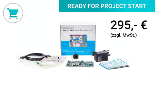
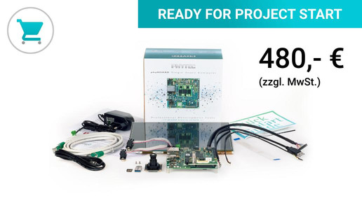
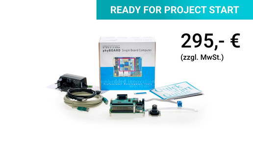
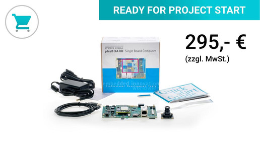
Total amount:
plus VAT.
NEW
VZ-018
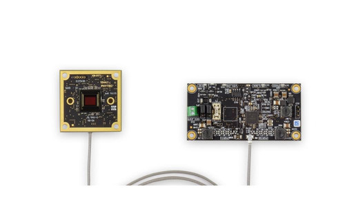
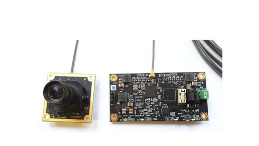
phyCAM-L to phyCAM-M Bridge
The converter for connecting phyCAM-L cameras (FPD-Link III) to a phyCAM-M interface
- phyCAM-L signals with a transmission path of up to 15m are converted into phyCAM-M signals
- FPD-Link III - standard
- power-over-coax
- optional second phyCAM-L connection
- external power supply possible
- Reference circuit diagrams for system integration included
With the new camera interface phyCAM-L, Phytec solves the problem of length restrictions of the MIPI CSI-2 interface. If the MIPI CSI-2 allows a maximum of approx. 15 cm between the camera module and the processor board, up to 15 m can be bridged with the phyCAM-L.
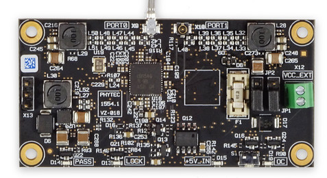
To process the signals from a phyCAM-L camera, a converter to MIPI CSI-2 is required on the processor side. This is usually not yet available on the application board in the evaluation phase. In this case - or for small series - the VZ-018 board is the solution. The phyCAM-M output of the converter can be connected directly to the phyCAM-M interface of the processor board. The board is electrically compatible with all embedded imaging kits with a phyCAM-M connector.
Exchangeable, flexible coaxial cables with UMCC Gen.1 connectors can be used as connection cables to the camera board (phyCAM-L). Adaptation to SMA or FAKRA plugs is also possible using pigtail adapters. The converter board has two phyCAM-L inputs. Two camera modules can optionally be switched to the phyCAM-M output.
The power supply for the camera module can be provided directly from the computer board via the phyCAM-M interface or, if required, it can be fed in externally on the converter board. The connection to the processor board is made via the 30 pin phyCAM-M connector.
An application note is available for easy integration of the converter circuit into a series product.
| Interface | 2 x phyCAM-L in, phyCAM-M out |
| Line Rate FPD-Link III | 4.0 Gbps per Rx port |
| Line Rate phyCAM-M | 4-lane with max. 1,6 Gbps per lane |
| Framerate | 5 MPixel @ 55fps |
| FPD-Link III Deserializer | TI DS90UB954 |
| Features | Power over Coaxial |
| Operating Voltage | 5…12 V DC |
| Power Consumption (max.) | 1200 mW |
| Operating Temperature | -25°C…+70°C |
| Connector Type (Signal in) | 2 x UMCC Gen.1, Coaxial |
| Connector Type (Signal out) | FFC/FPC 30 pin, 0.5 mm pitch |
| PCB Dimensions | 34 mm x 68 mm |
| Connector Type (Signal in) | 2 x UMCC Gen1, Coaxial |
| Connector Type (Signal out) | FFC/FPC 30 pin, 0.5 mm pitch |
| Mounting Points | 4 x M2.5 |


If you have any questions, please contact our technical sales department directly: +49 (0) 6131 9221-32
Our embedded experts are there for you!
Secure your personal consultation appointment quickly, easily and free of charge.
30 minutes exclusively for you and your project!
Education + Training _ Use our know-how for yours Productsdevelopment

With the know-how transfer from our experts to your developers, you will reach your goal faster!
Participants in our training courses receive a solid knowledge of professional hardware and software development.
Online seminars _ Helpful embedded knowledge explained in a nutshell in short video sessions

In informative online seminars with our experts and partners, we will inform you about exciting topics from the embedded industry.
You will get a free insight into new hardware and software solutions and learn more about special offers.
Other interesting topics: