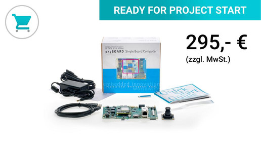
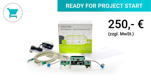
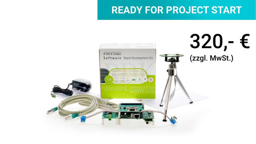
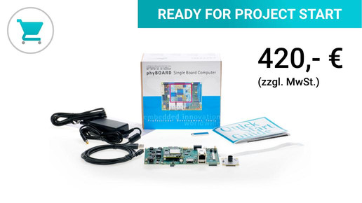
Total amount:
plus VAT.
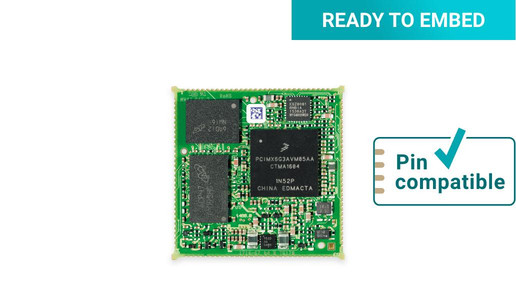
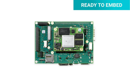
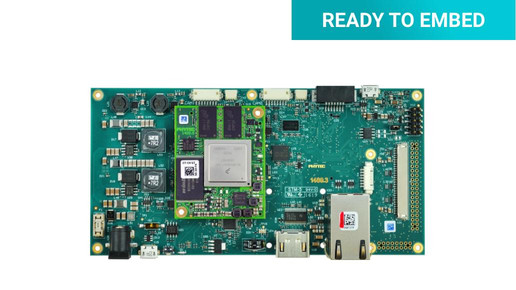
READY TO EMBED
phyCORE®-i.MX 6
ARM Cortex ™ -A9
The phyCORE-i.MX 6 is suitable for numerous industrial applications. Long-term available and proven many times over.
- Scalable: i.MX 6Solo to i.MX 6Quad 1.2 GHz
- Flexibility through soldering or plug technology
- Voice control engine
- MIPI CSI + camera parallel
- SATA
- LVDS, parallel 24-bit, HDMI
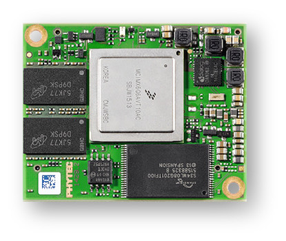
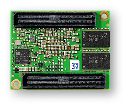
With the phyCORE-i.MX 6 you are choosing the smallest industrial i.MX 6 design on the market. The Cortex-A9 quad-core computing power is only 40 mm x 50 mm including PMIC. The module can optionally be equipped with SLC-NAND Flash or eMMC. Variants of the System on Modules in DSC technology are also available.
Release PD 6 is available for download as the Board Support Package for the phyCORE-i.MX 18.1 System on Module. The mainline BSP with kernel version 4.14 (LTS) offers open source graphics support via Etnaviv, extended camera support for our phyCAM-P and phyCAM-S Camera modules and the preparation of RAUC update mechanisms including a demo.
Already using the i.MX 6 module and now want to upgrade to the newer i.MX 8 processor family? Then use our instructions for your successful processor migration.
| Processor | i.MX 6Solo / i.MX 6DualLite / i.MX 6Dual / i.MX 6DualPlus / i.MX 6Quad / i.MX 6QuadPlus |
| Architecture | ARM Cortex-A9 |
| Bit width | 32 bit |
| Frequency | up to 1.2 GHz |
| Graphics | 3D GPU Vivante GC2000, 2D GPU Vivante GC355 (i.MX 6DualPlus - i.MX 6QuadPlus) |
| Video | 1080p decode and encode (i.MX 6DualPlus - i.MX 6QuadPlus) |
| Security | RNG, Ciphers, Security Control |


If you have any questions, please contact our technical sales department directly: +49 (0) 6131 9221-32
Additional advantages through extensive advance payments
Our embedded experts are there for you!
Secure your personal consultation appointment quickly, easily and free of charge.
30 minutes exclusively for you and your project!
Education + Training _ Use our know-how for yours Productsdevelopment

With the know-how transfer from our experts to your developers, you will reach your goal faster!
Participants in our training courses receive a solid knowledge of professional hardware and software development.
Online seminars _ Helpful embedded knowledge explained in a nutshell in short video sessions

In informative online seminars with our experts and partners, we will inform you about exciting topics from the embedded industry.
You will get a free insight into new hardware and software solutions and learn more about special offers.
Other interesting topics: